Detail the S.M.A.R.T of SSD
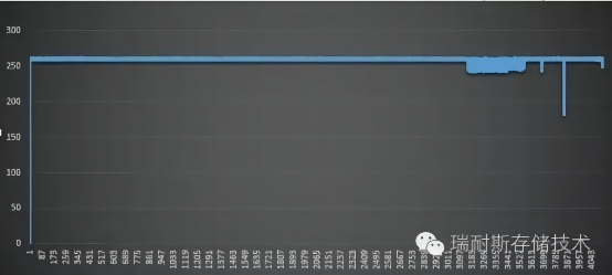
Before writing this article, we found that performance degradation occasionally happened to the SSD during the testing process. The S.M.A.R.T command was confirmed as the cause after the study. This is seemingly not critical, however, it may bring serious consequences of losing data packets if the SSD is applied in those critical domains like data acquisition, while of course this bug is correctable, first let us look at the screenshot:
S.M.A.R.T Overview
As the short for Self-Monitoring Analysis And Reporting Technology, S.M.A.R.T. can be read from its name with the function of fault alarm. The SSD health condition can be monitored and the parameter values can be fed back to the monitoring software or operating systems, in fact, most parameters are meaningful only for SSD engineers, the end users just need to focus on some key indexes, such as New Bad Blocks, Remaining Life and Erase Count, etc.
S.M.A.R.T information of the SSD can be obtained through some common testing software:
.png)
SSD controller manufacturers can also provide corresponding tools:
.png)
Through the years of continuous improvements by HDD manufacturers, some S.M.A.R.T standards are formed, however, for SSD, most S.M.A.R.T parameters are user-defined, thus the parameters provided by every manufacturer may be different, but generally, they refer to HDD S.M.A.R.T to set them.
The S.M.A.R.T information of SSD is saved in specific areas assigned by firmware, it could be in the area of OP (Over Provisioning) or possibly any area chosen by the firmware engineers, or saved with an independent table.
The S.M.A.R.T of SSD is not completely the same as that of HDD, those common testing software which can be got from the internet are designed based on HDD, SSD manufacturers usually make their own decisions to set S.M.A.R.T attributes according to the characteristics of NAND Flash.
Definition of S.M.A.R.T Indexes
01 Raw Read Error Rate
This index indicates the initial health condition of NAND Flash, the data values include correctable and uncorrectable errors.
09 Power-On Hours
The unit of measurement is generally an hour, it could be a minute or second, which is defined by SSD manufacturer. Usually, the time of all three states of work, idle and sleep are counted, some SSD solutions exclude the time of sleep by enabling some power management functions.
This parameter shows the accumulated power on time of the SSD, it is supposed to be 0 for a new SSD drive, while in fact the SSD manufacturers have already used for several or dozens of hundreds of hours during the testing process, it is just the parameter is resumed to be 0 by re-implanting firmware after the tests.
0C Power Cycle Count
The data value of Power Cycle Count means the power on/off cycle count for the SSD, it is usually just a few times for a new drive.
The power on/off for SSD is different to HDD, normally intense P/E cycle tests should be done for SSD, in addition, a large number of abnormal power off/on tests are required for military and industrial SSD to avoid the loss of mapping table or other unreliable factors which may be brought by abnormal power off. (3K to 10K abnormal power off/on cycle tests are done in Renice, but what users can read from the S.M.A.R.T reports is still a few power cycle count because the power cycle counts are cleared by re-implanting firmware after tests.)
B8 Initial Bad Block Count
Every NAND Flash has initial factory-marked bad blocks, the SSD firmware mark bad blocks by scanning 0xFF in the spare area of the first and the last page of each block, no mark of 0xFF expresses as bad block, bad blocks are managed by firmware uniformly and listed into bad block table.
The initial Bad Block Count reflects the initial health condition of the SSD on a certain level, the larger number of initial bad blocks represents the worse initial health status.
C3 Program Failure Block Count
When Program Failure happens to a page, the block of this page will be marked as bad block, this sort of bad block is named as new bad block and listed into the bad block management table. Every block has limited
Program/Erase cycle, program failures or erase failures push the block into the bad block table for centralized management. For those domains with extremely high requirements for data security, a block with just one program failure, erase failure or read failure will be marked as bad block.
C4 Erase Failure Block Count
The explanation is similar to C3.
C5 Read Failure Block Count
The explanation is similar to C3.
CA Total Count of Error bits from flash
This count includes Program Disturb Error, Read Disturb Error, Erase Error, and the total amount of correctable and uncorrectable error bits.
This value may looks very high, especially for the SSD with weaker ECC capability. Taking the parameter of CB into account, we can have a rough estimate about the ECC capability of the SSD, the larger value indicates the weaker ECC capability.
CB Total Count of Read Sectors with correctable bits errors
This count just includes the amount of the corrected error bits, so the number of uncorrectable error bits could be calculated by CA-CB, the bigger the difference between CA and CB, the weaker the error correction capability of the SSD is, and the shorter remaining life it represents.
CD Maximum PE Count
This parameter is set according to the specs in the datasheet of the NAND Flash, but in reality, the PE cycle of NAND Flash is larger than that listed in the datasheet, e.g. the provided value is 3,000, so the remaining life gets to 0 when the erase count reaches to 3,000, but the SSD actually remains in a healthy status. Hence this parameter is for reference of usage with the best insurance.
CE Minimum Erase Count
Maximum, Minimum and Average Erase Count describes the erase count of each block, the smaller the difference between the maximum and minimum value, the better the wear leveling algorithm it represents, and the average value makes no sense.
CF Maximum Erase Count
Refer to CE for the corresponding definition.
D0 Avage Erase Count
Refer to CE for the corresponding definition.
D1 Remaining Life (%)
This index shows the remaining life of the SSD, we can guess from the description of CD that this parameter is just a reference value, it doesn’t represent the true remaining life of the SSD.


